Posted on
Thin film deposition methods such as evaporation for indium bump deposition are often ideal for achieving good lift-off for patterned coatings. However, evaporation techniques can fall short of production needs for high-volume manufacturing. High-volume applications often require magnetron sputtering as a deposition method.
The challenge for these manufacturers is to achieve good lift-off while meeting demands for high throughput.
Sputtering Process for Lift-Off Applications
Semiconductor applications nearly always require an automated thin film deposition process for high-volume manufacturing. A magnetron sputtering system with cluster architecture is the ideal solution for compound semiconductors. With this configuration, compound semi manufacturers get all the benefits of a cluster tool, such as multilayer coatings and a dedicated module for pre-cleaning, as well as the potential to create nanostructures with excellent lift-off.
Sputtering is not necessarily conducive to achieving good lift-off. If this capability isn’t designed in with good collimation control, it can affect yield and production output. These are both particularly important factors for minimizing cost of ownership in high-volume manufacturing.
Improving Lift-Off in Magnetron Sputtering
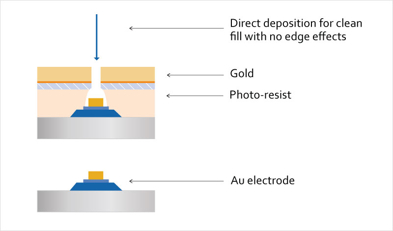
The biggest factor that affects lift-off in magnetron sputtering is system geometry. Here is what you need to consider to achieve the optimal geometry for collimation control and lift-off:
- Deposition angle and angular distribution: Clean lift-off requires well-collimated (low angular distribution) deposition perpendicular to the wafer. The typical collimation requirement is an angular distribution of less than 7°. While there are several benefits to confocal cathode orientation during sputtering, this set-up will not deliver very good lift-off because the incident angle is generally about 30°. For the best lift-off, the sputtering direction needs to be either straight up or straight down, which occurs with a vertical sputtering configuration. A physical collimator can be used to limit the angular distribution. However, at the normal sputtering throw distance (around 10cm) there is significant buildup of high-angle material on the collimator, and the collimator is inside the magnetron plasma. This can lead to unacceptable levels of particle generation.
- Pressure: Pressure is always a consideration for lift-off but particularly so in magnetron sputtering. Compared to evaporation, chamber pressure is much higher during sputtering. Higher pressure leads to more collisions between background gas and the sputtered material, which degrades the collimation. An optimized magnetron behind the target can assist with operating at a lower pressure than the typical milliTorr range for these systems.
- Throw distance: A longer throw distance between the target and substrate is needed to ensure collimation control. Longer throw implies more collisions and a degraded collimation, so the pressure needs to be very low to counterbalance that effect.
An ideal way to address both throw distance and pressure needs for good lift-off is through dual collimation, where an intermediate throw (between standard and long throw) and a physical collimator are used together. The dual collimation technique reduces the throw and places the collimator close to the wafer to achieve an acceptable collimation. This eliminates the need for operating at a very low pressure. It also reduces the build-up on the collimator and positions it out of the plasma so the collimator sees less heat, which minimizes particle generation.
Achieving high collimation for good lift-off will necessarily slow the deposition rate compared to standard throw sputtering. However, for high-volume manufacturing, sputtering is completely compatible with standard automation solutions and cluster tool architectures. This can be a significant advantage compared to evaporation.
To learn more about addressing thin film deposition needs in high-volume manufacturing, download Denton Vacuum’s white paper.